Things I hope you learn from this post series:
- Part 1: Why do we use fiber optic cables?
- Part 2: What is a fiber?
- Part 3 (you are here): The very basics of optical communication, but also some super advanced stuff
Now that you understand the basics of fiber optics, let's learn how to actually transmit information through a fiber optic cable. This part of the series will focus on the transmitting side of an optical communication system. We'll start small (clicking on and off a flashlight really-really-fast), and end with the state-of-the-art in optical communication (a mouthful: probabilistically-shaped quadrature amplitude modulation)
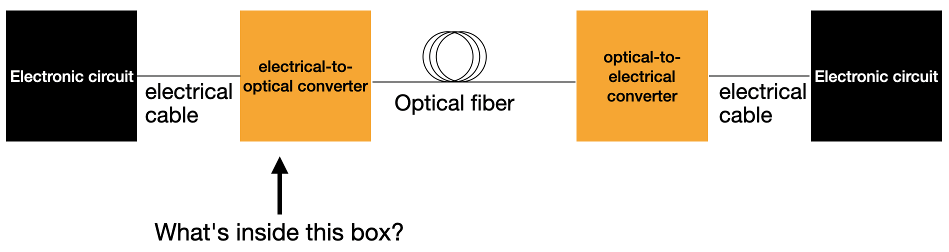
An abstract optical link starts with some electronic circuit (such as in the network interface card in a server) and some sort of electrical connection from that circuit to an electrical-to-optical (electrooptic) converter. This converter takes the electrical signal on one side and imparts that information onto light on the other side. Often, this is called "modulation" since some property of the light, such as its intensity, is modulated (light-on == "1" / light-off == "0"). The modulated optical signal then propagates down an optical fiber to an optical-to-electrical converter which is then connected to some sort of electronic circuit on the other side.
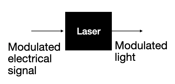
There are a lot of ways to use an electrical signal to modulate an optical signal. The simplest you might imagine looks like a light switch. The single-mode-fiber analogue to that is directly turning on and off a laser, which are typically single-mode devices. This is called a "directly modulated laser" or DML:
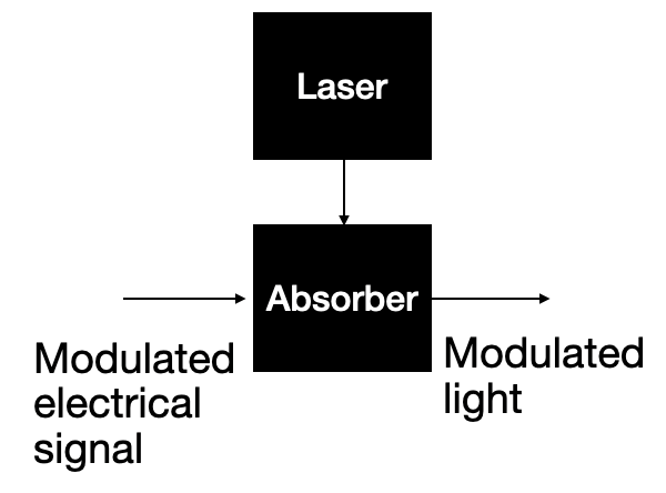
Alternatively, you could shine light through a material that absorbs light, and whose absorption properties can be electrically controlled. This is called an "externally modulated laser" or EML:
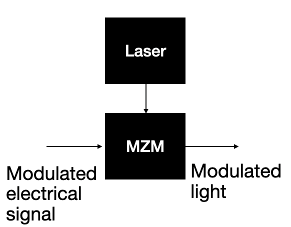
Another method to create modulation is with an optical interferometer. (This may or may not have been in your high school or college physics class. I'll give a brief review in a second). The most common type of interferometer used for modulation is the Mach-Zehnder modulator or MZM.
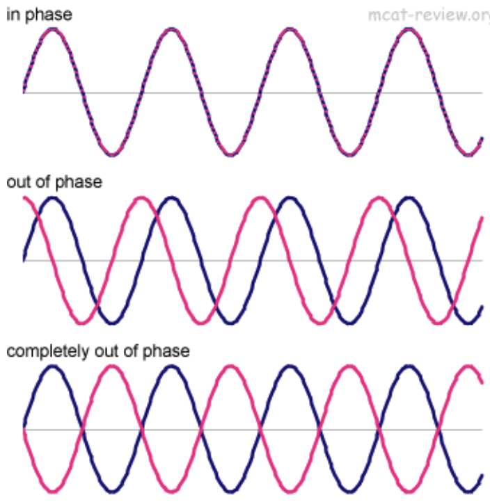
Recall (or learn for the first time right now), that light has both an amplitude and a phase. When we say that two optical beams are "in-phase" we mean that there is no difference in their relative phases. Similarly, every other relative phase difference is described as "out-of-phase." If a laser is split and then re-combined with both of the split beams being in-phase, the original laser beam can be recovered as if it were never split. Sometimes we call this "constructive interference." If instead, the two split beams of light are are combined while completely-out-of-phase, there will be no light at the output of the combiner--"destructive interference."
Using this concept of constructive and destructive interference, we can create a device that modulates the light output if we are able to modulate the relative phase of the light in the two paths. One of the most common interferometers is the Mach-Zehnder interferometer (MZI), shown below. There exist materials and devices that change their optical properties through an electrical stimulus, and we can use these inside of an MZI. As the phase in one of the paths is changed from 0° to 360°, the intensity of light at the detector changes in a sinusoidal pattern, with a null point where the two beams in the two paths are out of phase, and the peak where they are in-phase. The "quadrature" point is a fancy way of saying the phase is set to halfway between out-of-phase and in-phase where the intensity of light detected is half of what it is at the peak.
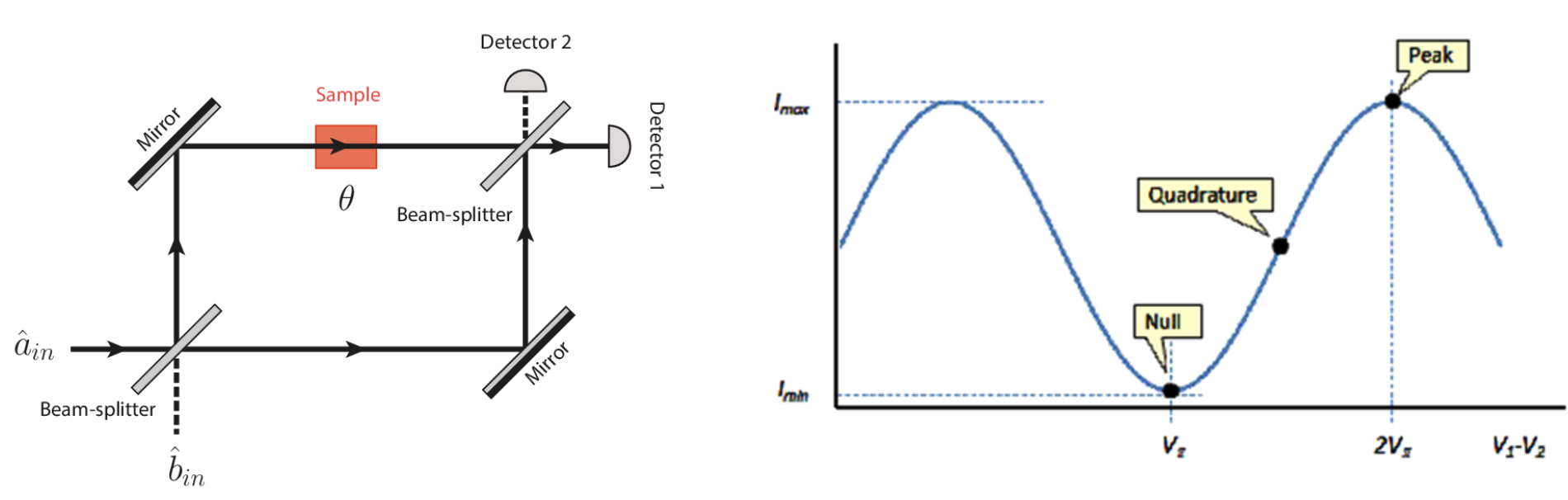
If we were to adjust that phase change in time around the quadrature point, we will see modulated light at the output of the Mach-Zehnder inteferometer. By changing, or modulating, the electrical input in in this way, we have created an optical modulator
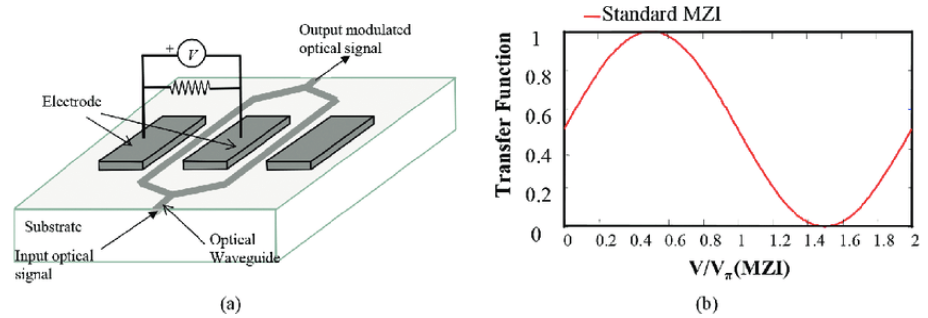
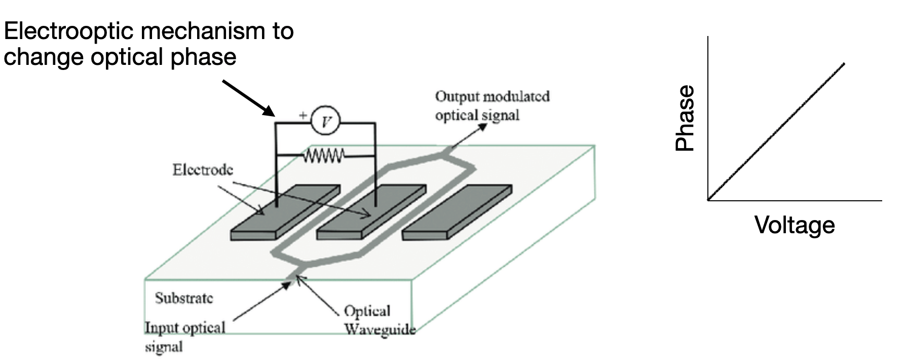
One common material used to make Mach-Zehnder modulators is lithium niobate, or LiNbO3. Real lithium niobate modulators look surprisingly close to the below cartoon of one. Depending on the orientation of the lithium niobate crystal, the refractive index of the device will change in the presence of an electrical voltage.
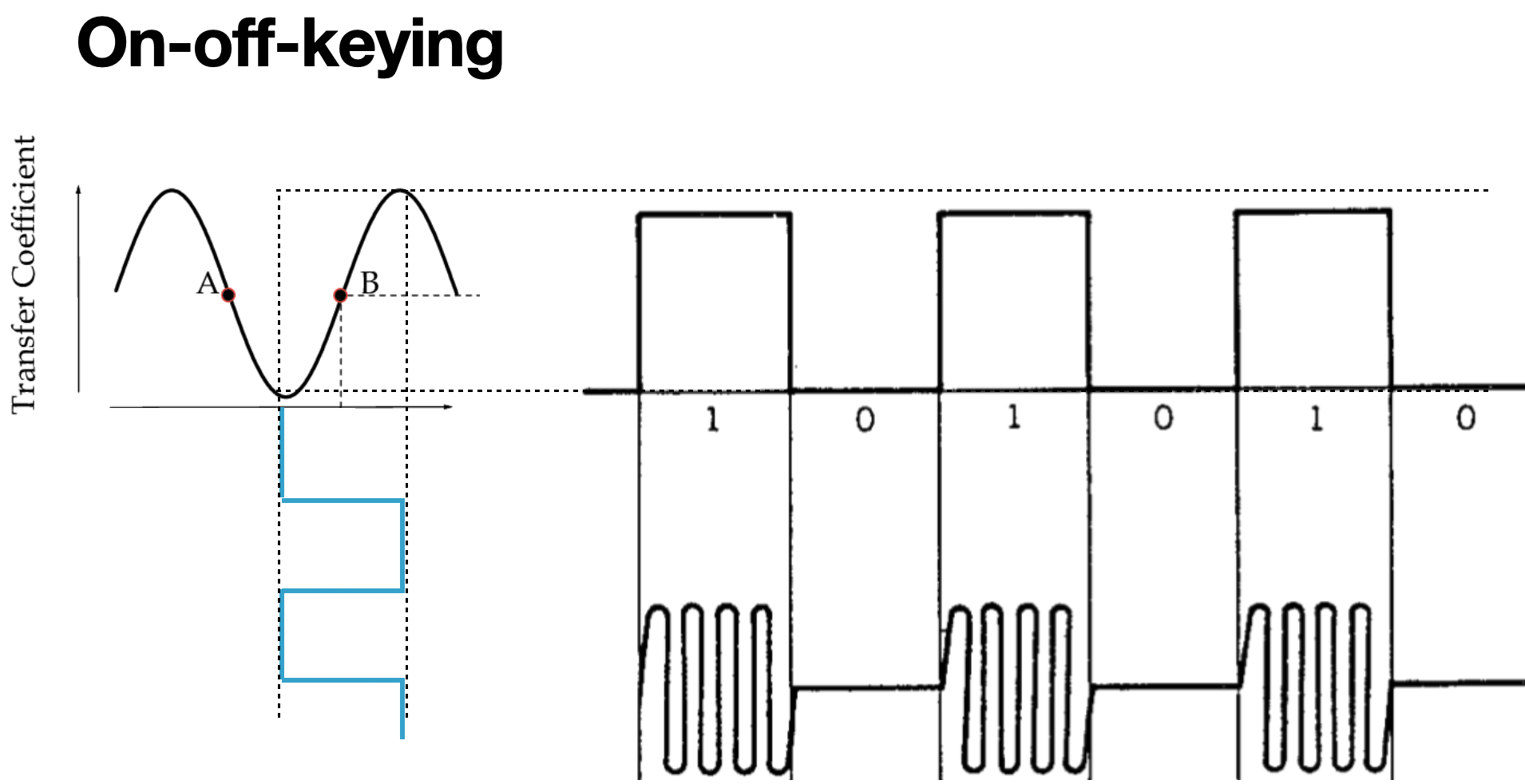
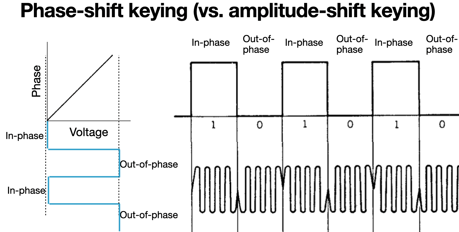
Now we can take this MZM, and drive a binary voltage signal into the input and at the output see a binary optical signal. I included a sinusoidal picture beneath the square wave optical output to remind you that light has both an amplitude and a phase, because we will be using that concept in a second. The encoding scheme of using the presence or absence of light to represent our "1"s and "0"s is often referred to as "on-off-keying," because we have "keyed" our information with a light that is either on or off. Sometimes you might see this referred to as "amplitude-shift-keying" (ASK), for similar reasons.
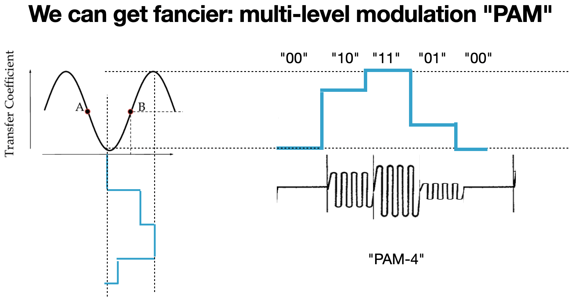
We can get fancier, though. We don't have to settle for a binary input and output signal. Since the MZM is fundamentally analog, we can input a multi-level input signal and detect a multi-level output signal. As long as we have a receiver that can distinguish between the different levels, we can transmit twice (or more) as much information per transition as before. In this case, we start referring to the received signal as "symbols" rather than "bits," since the data is more than just binary per transition. This type of multilevel modulation is sometimes referred to as "pulse amplitude modulation" (PAM), or still as ASK. This example with 4 levels is sometimes referred to as PAM-4 or 4-ASK. The difference between ASK and PAM when we are talking about optical signals is not that important.
Well, there's more to light than just its amplitude, remember? Light also has a phase, and we have a method of changing its phase. If we had a reference laser to compare against, we could say that light that is in-phase with that reference is a digital "1" and light that is out of phase with that reference is a digital "0". This is the so-called "coherent" part of the title of this blog post series. We use "coherent" in this context to describe an optical signal that can be repeatably interfered with a reference beam because it has some deterministic phase. Incoherent light has random phase properties, making things like interference impossible.
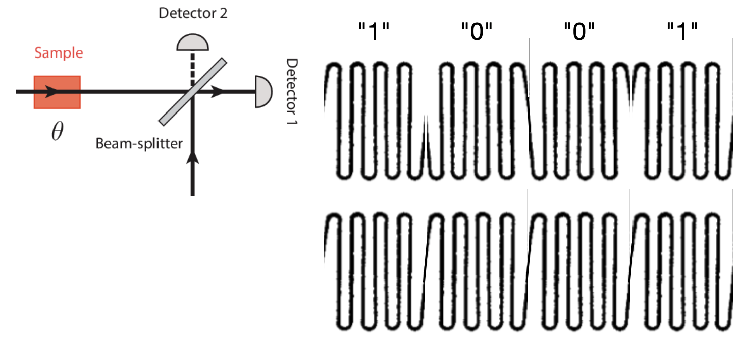
We can detect this relative phase information by using an interferometer. Instead of taking light and splitting it, we can instead skip the splitting step and directly try to combine it with a reference beam of light
Coming back to that lithium niobate modulator, we can see we already have an electrooptic mechanism to change optical phase. In this case, the phase change is directly related to the voltage.
And just as before, we can apply a binary voltage input to our phase modulator and see a binary change in the output phase. We can interfere that optical signal with a reference signal and create "1"s and "0"s where our optical signal and the reference signal constructively or destructively interfere with one another. This is now phase-shift-keying because the information is keyed on the optical phase, as opposed to encoding information in the optical amplitude in amplitude-shift-keying.
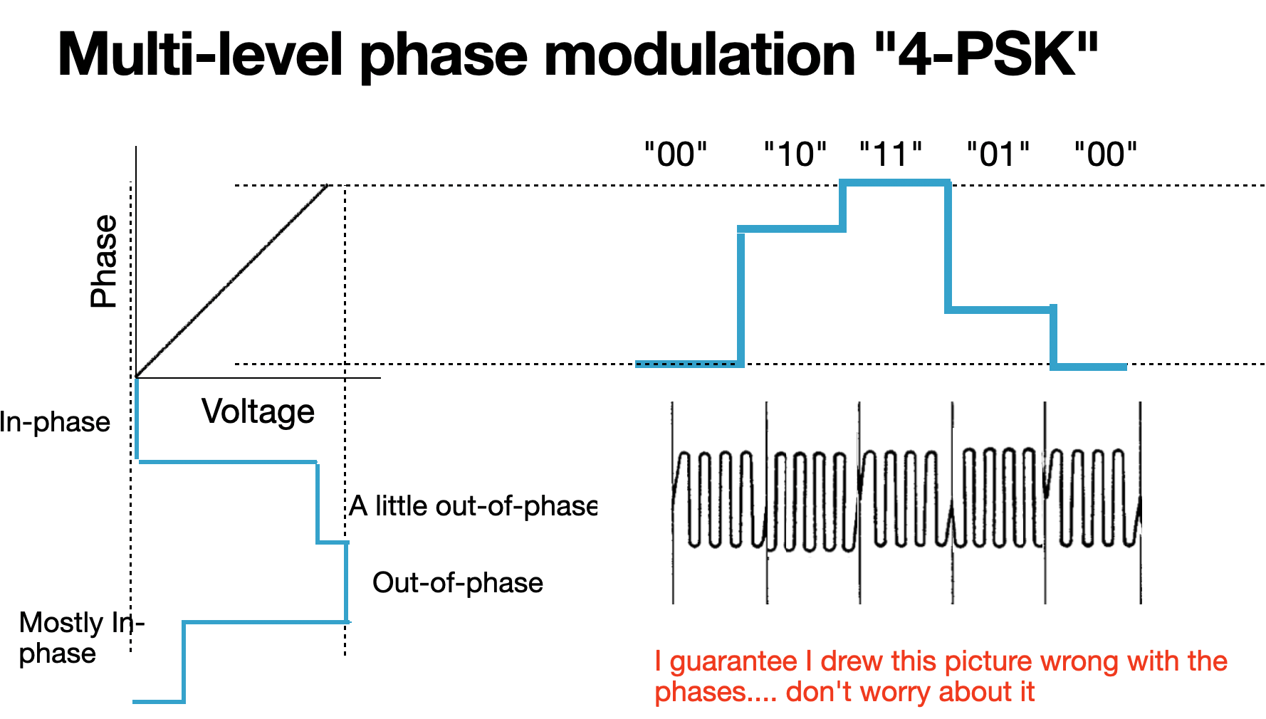
And just as before, we can apply multilevel voltage inputs to our phase modulator to create multilevel phase outputs. Similar to 4-ASK, we can create a 4-PSK signal. In practice, we use a more complicated optical structure to modulate phase, rather than a simple linear phase shifter. Perhaps I will describe how this is done in some future blog post.
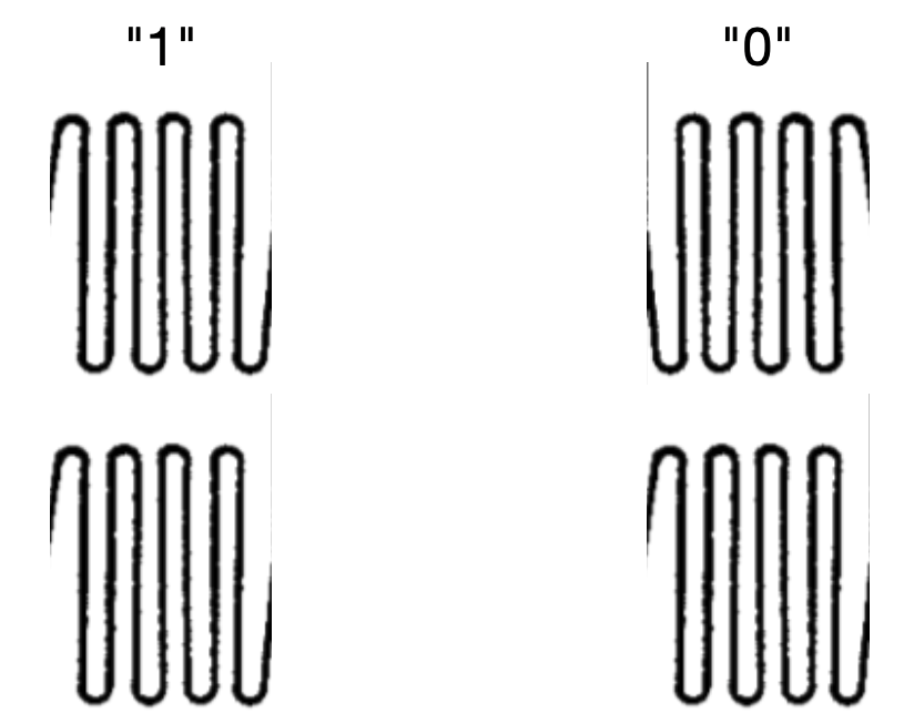
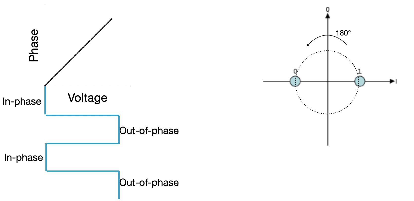
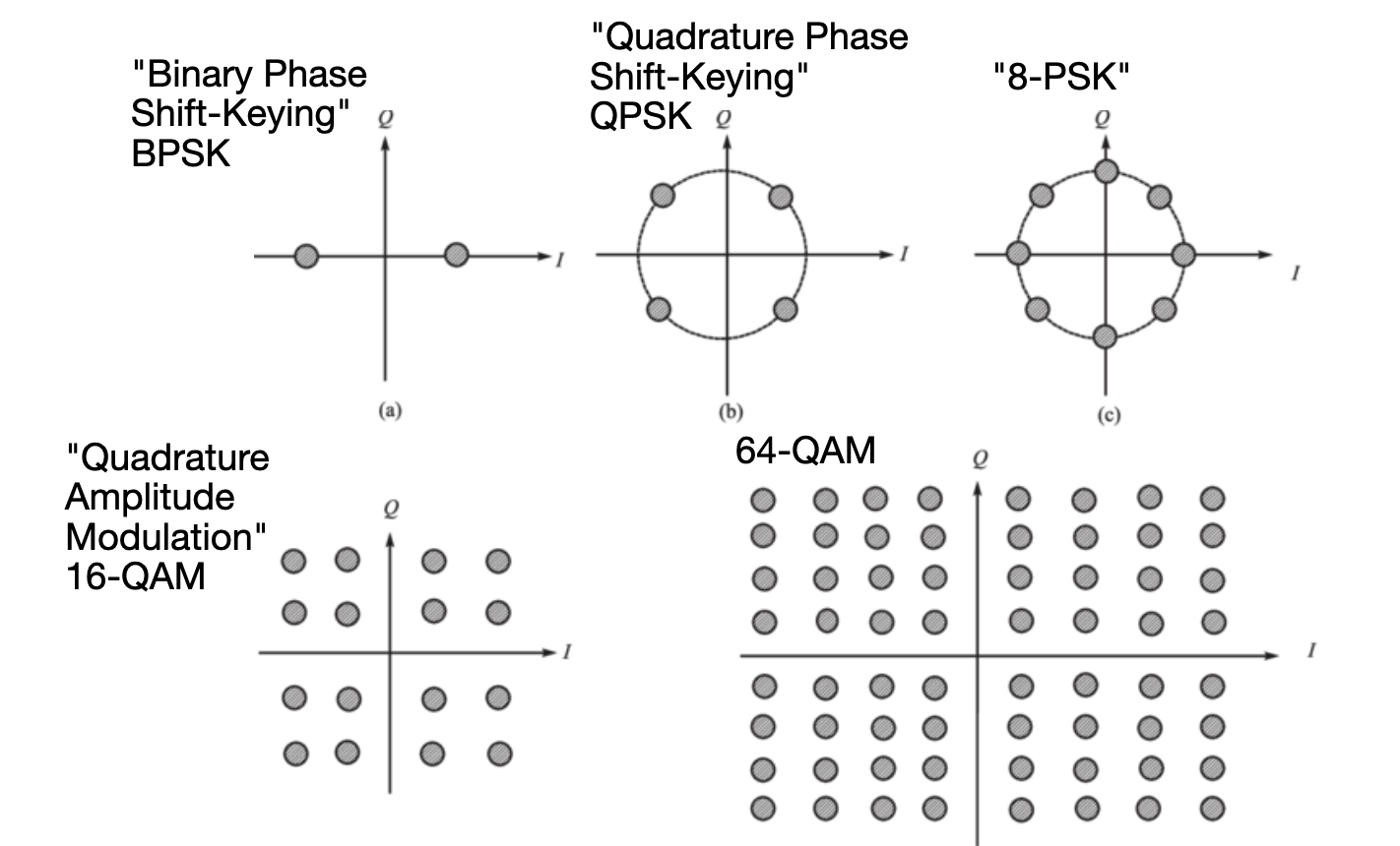
Keeping track of the phase visually for display on pages like this can be challenging. It can be helpful to draw a circle and point to locations on the circle as the relative phase. In the case where there are two possible phases, 180° apart from one another, we draw two points on opposite sides of a circle:
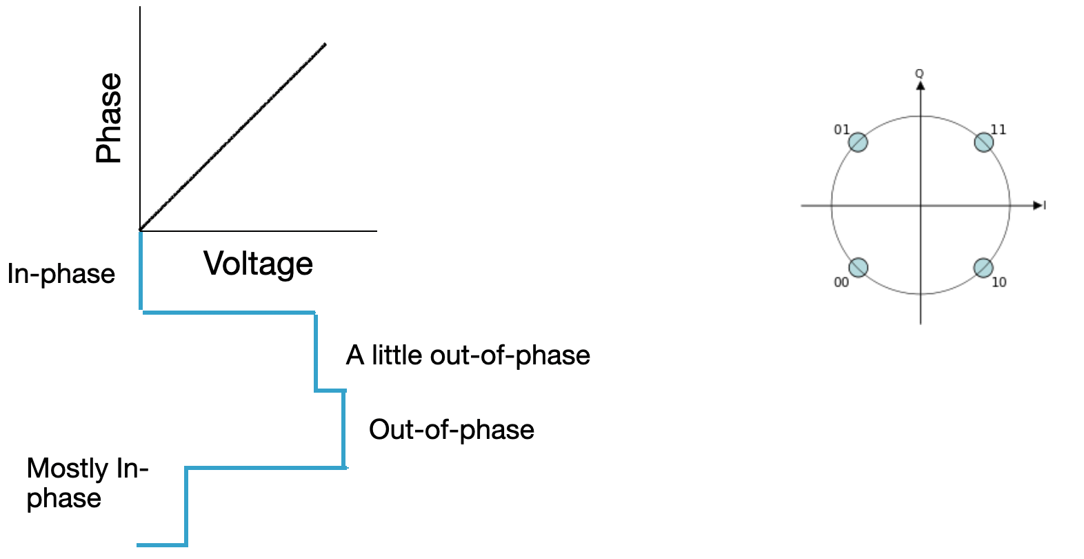
And for 4-PSK where there are 4 possible phases, each 90° apart from one another, we draw 4 points on the circle:
This is where that two-dimensional visualization of phase is useful: we can encode information on both the amplitude of light and the phase of light at the same time! If the light is brighter, we draw a bigger circle. If the light is dimmer, and 180° out of phase, we draw a point 180° away closer to the center of the graph. This type of modulation is called "quadrature amplitude modulation" (QAM). The case where we have 4 amplitude levels and 4 phase levels is called 16-QAM, because there are 16 possible received optical states.
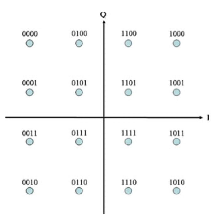
We don't have to stop at 16-QAM, if our receiver is capable-enough, we can continue to add amplitude and phase levels until the points start to blur together.
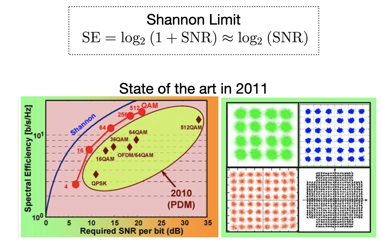
The concept of "until the points start to blur together" is important. Nothing in life is perfect (except, perhaps, April 25th), and so there will always be "noise" on our signal going into the receiver. We can never drive the amplitudes and phases exactly right, and the electronics themselves create random fluctuations in our signals. You could imagine that for 64-QAM, if all the points are too fuzzy, you couldn't tell one point from another. The amount of "signal" we have compared to the amount of fuzziness, or "noise," is often expressed as a signal-to-noise ratio (SNR). Claude Shannon famously described an upper limit to how much information could theoretically be transmitted in a link given some (SNR) of the received signal. Coherent communication gets us pretty close to that theoretical limit--within a factor of 5 or so demonstrated in 2010.
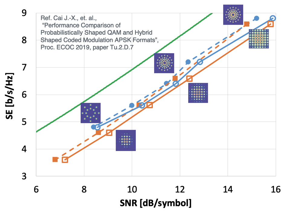
Nine years later, in 2019, and we can get pretty darn close with even fancier modulation schemes. These schemes still encode information in the amplitude and phase of light, but they both distribute the points differently and use each point with different probabilities. They are "probabilistically-shaped" in that the points closer to zero are used more often than the points farther away. With these types of techniques, we can get to within a factor of 2 away from the theoretical limit of spectral efficiency
Looking back at the last 150 years of long-distance communication and 40 years of optical communication, the scaling factor is astounding. A variety of fundamental breakthroughs over the years has enabled a roughly yearly doubling in the capacity of our communications systems (expressed in those now-familiar-to-you terms of data rate times distance product).
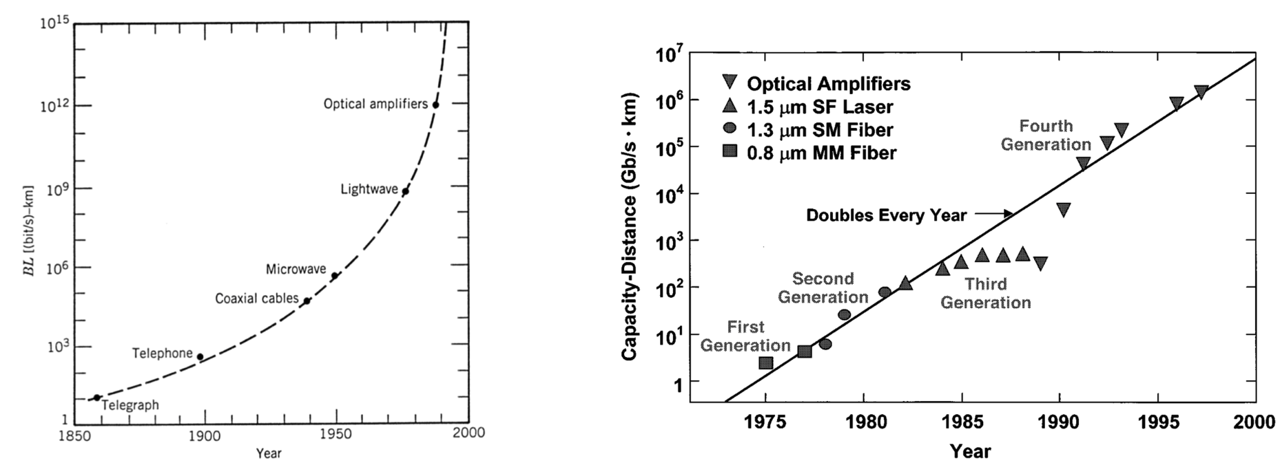
(right) H. Kogelnik, “High-capacity optical communications: personal recollections,” IEEE Journal of Selected Topics in Quantum Electronics, vol. 6, no. 6, pp. 1279–1286, Nov. 2000
What is actually deployed in the field has kept close pace with research. The first systems deployed into the internet that you know often follow the first research demonstration within about 4 years. The modulation formats we just talked about are very likely carrying these text characters to your computer. 4-PSK (also known as QPSK) at 100 Gbps was first deployed in 2010, with 16-QAM systems operating at 200 Gbps being deployed shortly thereafter in 2013. In 2020, there are published results in excess of 1 Tbps on a single wavelength, and more than 100 Tbps total in a single fiber.
What about the fiber coming to your dream house? Why can't you get a 1 Tbps connection? It's coming, but at a different rate. The data rate of those access networks has been scaling at between 30% and 50% per year. Those connections don't use these advanced modulation formats we just discussed. They're optimized for cost at a lower data rate.
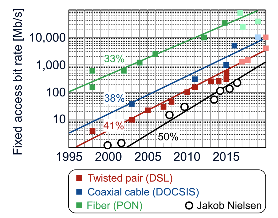
J. Nielsen, “Nielsen’s Law of Internet Bandwidth,” Apr. 5, 1998. [On- line]. Available: https://www.nngroup.com/articles/law-of-bandwidth/
As I read back through this post series, there are hundreds of neat little details that I glossed over that all deserve their own dedicated post. I hope this post series was useful/informative/not-factually-incorrect for you. Feel free to email me any comments!