Things I hope you learn from this post series:
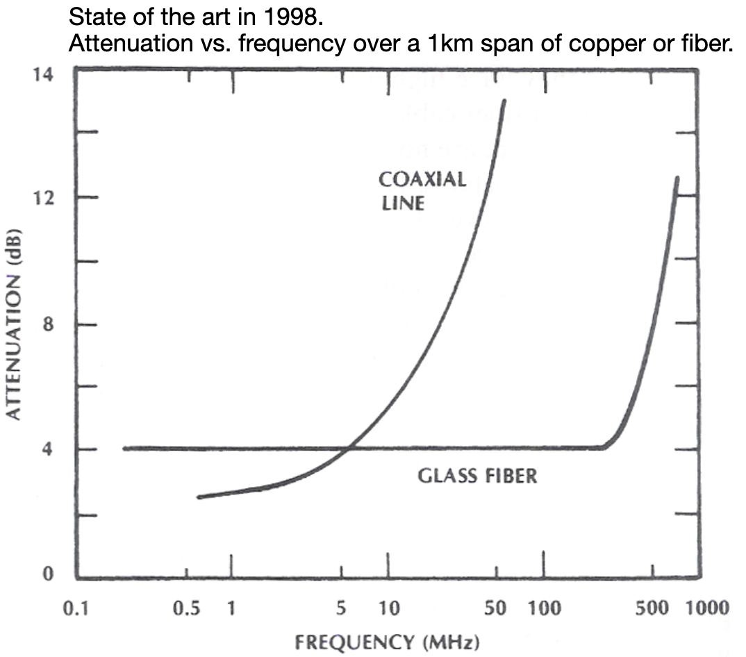
- Part 1: Why do we use fiber optic cables?
- Part 2 (you are here): What is a fiber?
- Part 3: The very basics of optical communication, but also some super advanced stuff
This part of the post series will actually touch more on the question of "why is a fiber?" than "what is a fiber?" I will show a cross-section of a fiber-optic cable down below, but to understand the why of how it looks is, I think, more important. If you just want a pretty picture of a cross-section, skip ahead.
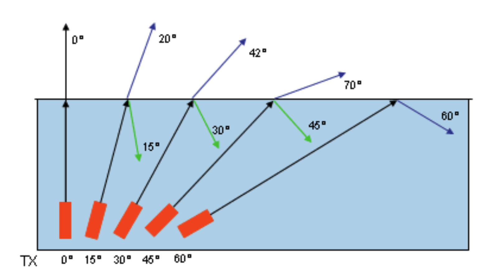
To begin, recall total internal reflection (possibly from high school physics? Though, I know shining light down a water stream is a common elementary school science demo). The gist of total internal reflection is that light will either be reflected or transmitted at the interface between two materials, depending on the wavelength, angle of incidence, and relative refractive indices of the two materials:
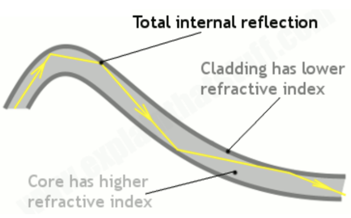
If we can create a "tube" or "fiber" of high-refractive-index material surrounded by low-refractive-index material, we can use total internal reflection to keep light inside of this "optical fiber." (Representing light propagating in fibers as "rays" is a simplification, but we'll stick with it for now)
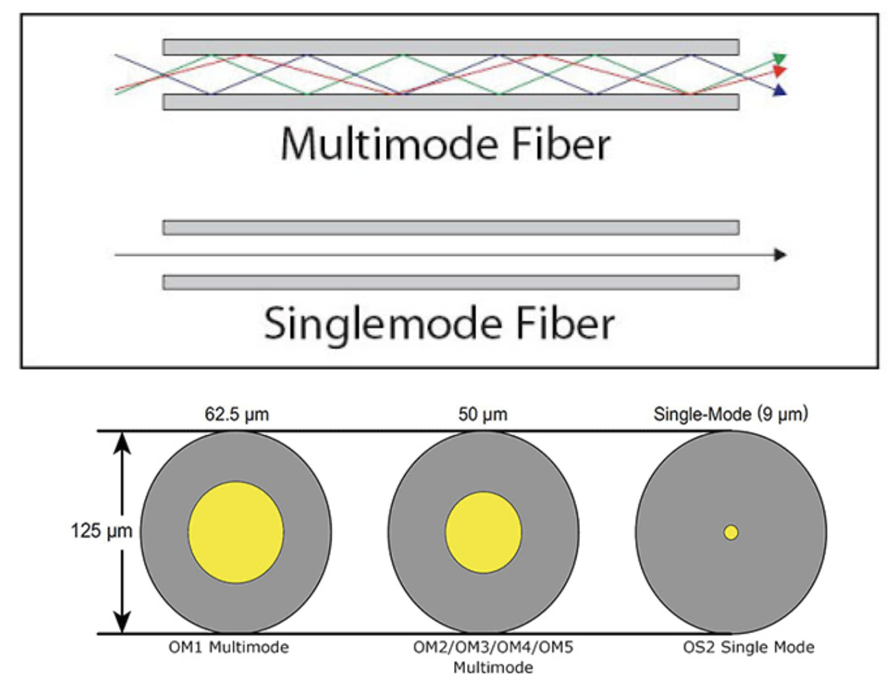
A cross-section of a fiber will show a central core (the high-refractive-index part where light is guided), a low-refractive-index cladding, and layers of strengthening material around the cladding.

The coating, "strength member," and outer jacket are purely to protect the inner core and cladding from environmental factors, primarily backhoes. All of the optical magic happens in the core, interface between the core and cladding, and the cladding just surrounding the core. For reference, a typical human hair is around 50 µm in diameter.
There are many different kinds of fiber optic cables. For now, we will lump them into two categories: "multi-mode" fiber (MMF) and "single-mode" fiber (SMF). Multi-mode fiber has larger cores. You can see that with a large core, there are many possible paths for the ray of light to take as it propagates through this fiber. Each of those "paths" that the light can take is called an "optical mode" by physicists. (Again, simplification, but it works for now). As the core of the fiber gets narrower and narrower, eventually there is only one possible path the light can take: a single "mode."
There are a few reasons why we might use MMF in one application and SMF in another. For one, you can imagine that it is a lot easier to get light into the core of an MMF fiber than an SMF. But, all of those modes in a multi-mode fiber cause a crucial problem. Looking at the picture of all those rays propagating in the core of MMF, you can trace out that some will be longer than others. Depending on how you shine the light into your fiber (and other qualities of the input light that we won't go into here), you will receive your signal after different amounts of delay.
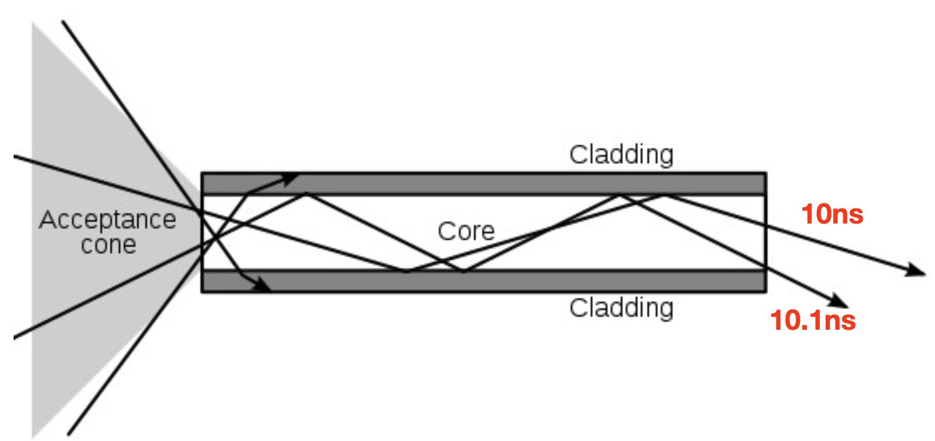
The phenomenon where your input signal could come out the other end of your MMF cable over disperse periods of time is called modal dispersion. This limits the maximum switching speed times cable length product that the fiber is good for. Since the variable time it takes to transit your cable depends on length, a long cable will cause a large amount of variability. In order to receive your signal successfully, you have to switch at a slow enough speed so that you can be sure to account for any variation in how long the different paths take to transit the cable. Similarly, if the cable length is very short, you can switch your light source on and off very quickly because the variable delay isn't an issue.
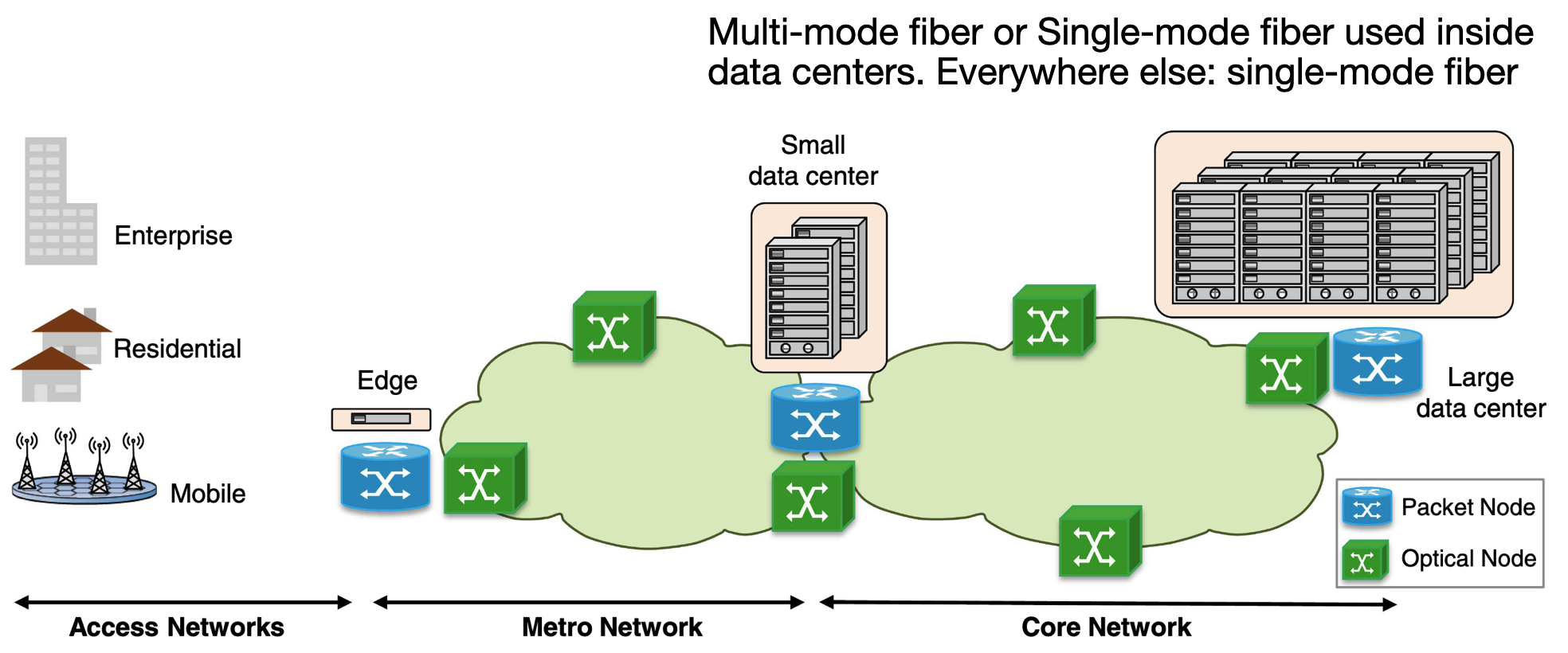
Over the years, various advancements in multi-mode fiber, transmitters, and receivers, have pushed the limits of what can be achieved. Modern OM4 fiber can transmit data at 100 Gbps over 150 meters, which is good enough for applications inside many data centers. However, for anything requiring longer reaches SMF is the way to go. Many large data centers will use SMF where reaches of up to 1 or 2 km are needed, and future re-use of the fiber plant infrastructure is a bonus. Returning to the network architecture figure I borrowed from a paper in part 1, most of the connections in the picture are made with SMF cables.
In the next part of this series, we'll discuss how to actually generate these optical signals propagating in optical fibers.
On to part 3: the very basics of optical communication but also some super advanced stuff!